RF Propagation & Spectrum Reach Intelligence
Terrain-aware, weather-degraded RF propagation modeling: coverage, link budgets, emitter location, and cellular reach planning.
The Problem
RF propagation is the invisible architecture of every modern operation. Whether you're planning jammer placement, assessing cellular coverage along a convoy route, estimating where an unknown emitter might be transmitting from, or validating that your UAS will maintain command-and-control link throughout a BVLOS mission - the answer depends on how radio waves interact with terrain, atmosphere, and the built environment.
Most tools give you a circle on a map. "This radio covers 10 km." That's a free-space assumption that ignores the ridge between you and the target, the rain that's attenuating your Ku-band link, and the urban canyon that's creating a 20 dB shadow zone on the east side of the objective.
Empyrean doesn't draw circles. It computes terrain-shaped, weather-aware, physics-grounded RF coverage that reflects what the electromagnetic environment actually looks like - not what it would look like in a vacuum.
Modules Used
- EMSO (Electromagnetic Spectrum Operations) - propagation modeling engine, emitter range estimation, reception envelope analysis, cellular operations, and spectrum management
- Common Operational Picture - inline propagation context on track cards, coverage overlays, and cellular infrastructure visualization
- Fusion & Decision Engine - weather-degraded sensor models, C2 link budget assessment along UAS routes, and confidence scoring that accounts for propagation uncertainty
- Weather Intelligence Service - live atmospheric conditions feeding ITU-R attenuation models for realistic RF predictions
- Space Situational Awareness - space weather impact on HF propagation, GPS accuracy, and SATCOM link reliability
The Physics Stack
Empyrean implements a layered propagation architecture. Each layer adds fidelity, and operators choose the appropriate level for their use case - from quick planning estimates to high-fidelity terrain-aware analysis.
Layer 1: Analytical Path Loss Models
Four validated empirical and theoretical models cover the full frequency spectrum:
Free-Space Path Loss (FSPL) is the Friis transmission equation - the theoretical minimum loss for any RF link. Useful as a baseline and for space or air-to-air paths with clear line of sight. Works at any frequency.
Okumura-Hata (150-1500 MHz) is the workhorse empirical model for VHF/UHF macro-cell propagation. Derived from Okumura's extensive Tokyo measurement campaigns (1968) and Hata's closed-form approximation (1980), it accounts for urban, suburban, and rural environments with empirically validated correction factors. This is where most tactical radios, P25 public safety systems, and legacy cellular live.
COST-231 Hata (1500-2000 MHz) is the European extension of Hata for PCS/DCS bands, developed by the EURO-COST 231 committee (1999) for the 1.8-2.0 GHz cellular bands. Adds a metropolitan correction factor for dense urban environments.
3GPP TR 38.901 (Sub-6 GHz through FR2) is the modern 5G channel model from 3GPP Technical Report 38.901 V16.1.0 (2020). Covers frequencies from 500 MHz to 100 GHz with explicit LOS/NLOS path states and Urban Macrocell (UMa) geometry with 3D distance computation. This is the model for 5G NR, LTE-Advanced, and millimeter-wave planning.
All four models are implemented in a high-performance computation kernel that enables real-time interactive analysis at batch scale - 10,000+ simultaneous path loss computations without pre-computation delays.
Layer 2: Terrain-Aware Propagation
When terrain data is available (SRTM, DTED, or uploaded GeoTIFF), Empyrean switches from circular coverage assumptions to terrain-shaped reality:
Fresnel Zone and Knife-Edge Diffraction is based on ITU-R Recommendation P.526-15 (2019). The engine computes first Fresnel zone clearance along the propagation path, identifies terrain obstructions, and applies knife-edge diffraction loss using the Fresnel-Kirchhoff parameter. The 60% first-Fresnel-zone clearance criterion determines whether a path has adequate clearance for negligible diffraction loss.
ITM / Longley-Rice is the Irregular Terrain Model from NTIA Report 82-100 (Hufford, Longley, Kissick, 1982) - the gold standard for long-range propagation over irregular terrain. It combines effective antenna heights, smooth-earth horizon distances, terrain irregularity, and Deygout multi-edge diffraction (1966) for beyond-horizon paths. The model automatically selects between line-of-sight, diffraction, and tropospheric scatter regimes based on path geometry.
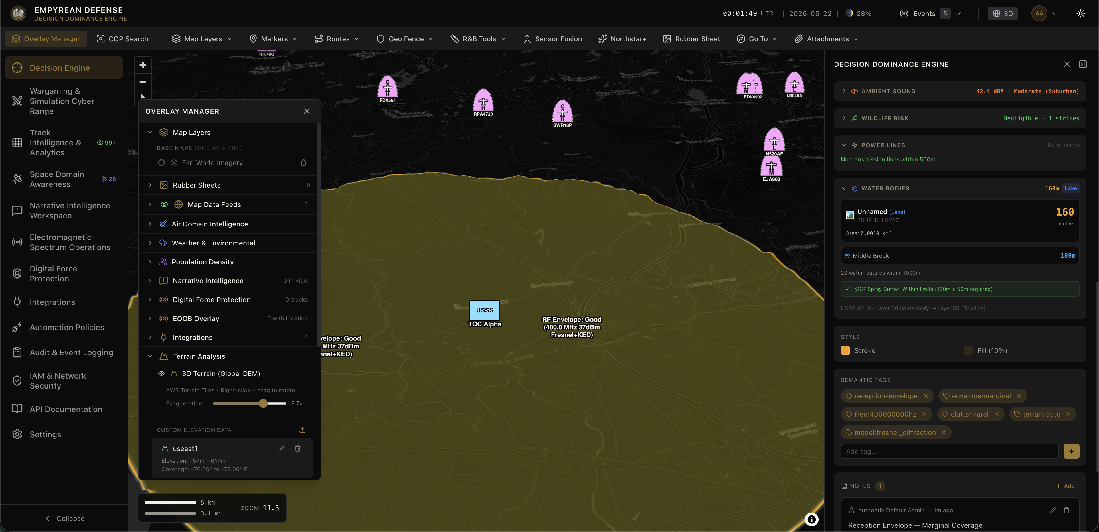
The terrain engine marches outward along configurable radials (default: 360 azimuths at 100m steps), evaluating the full link budget at each point. The result is a non-circular, terrain-shaped coverage polygon that shows operators exactly where their signal reaches and where terrain blocks it.
Layer 3: Atmospheric and Weather Effects
Live weather data from the Weather Intelligence Service feeds directly into the propagation engine through ITU-R atmospheric models:
ITU-R P.676-13 (2022) for gaseous attenuation models oxygen absorption (critical peak at 60 GHz) and water vapor absorption (22.235 GHz rotational resonance). Below 10 GHz, atmospheric gas attenuation is negligible. Above 10 GHz, it becomes operationally significant and frequency-dependent.
ITU-R P.838-3 (2005) for rain attenuation applies the power-law specific attenuation model, where rain rate in mm/hr drives frequency-interpolated dB/km loss using ITU-R coefficients. When it's raining at 25 mm/hr, your 5.8 GHz C2 link doesn't cover what it covered an hour ago - and the platform shows you the difference in real time.
When weather-aware mode is enabled, the max-range solver iterates with atmospheric loss included at each distance step, converging on the true weather-degraded coverage rather than a clear-sky assumption with a manual fade margin bolted on.
How It Works
Emitter Range Estimation (Reverse Propagation)
You've detected an unknown signal at -72 dBm on 450 MHz. Where is the transmitter?
Traditional approach: draw a circle at the theoretical max range. Empyrean's approach: invert the propagation model. Given the received power, assumed transmitter power bracket (from spectrum management templates or operator judgment), and the propagation environment, the engine solves for distance. The result is an annulus representing the probable emitter location band between minimum and maximum estimated range.
In terrain-aware mode, this becomes a non-circular, terrain-shaped annulus. Per-radial data is returned for operator reasoning - you can see exactly which azimuths have terrain advantage and which are blocked.
This feeds directly into the Electronic Order of Battle. Assessed emitter entries get physics-grounded range estimates that update as conditions change.
Reception Envelope Analysis
"What does my sensor actually cover right now?"
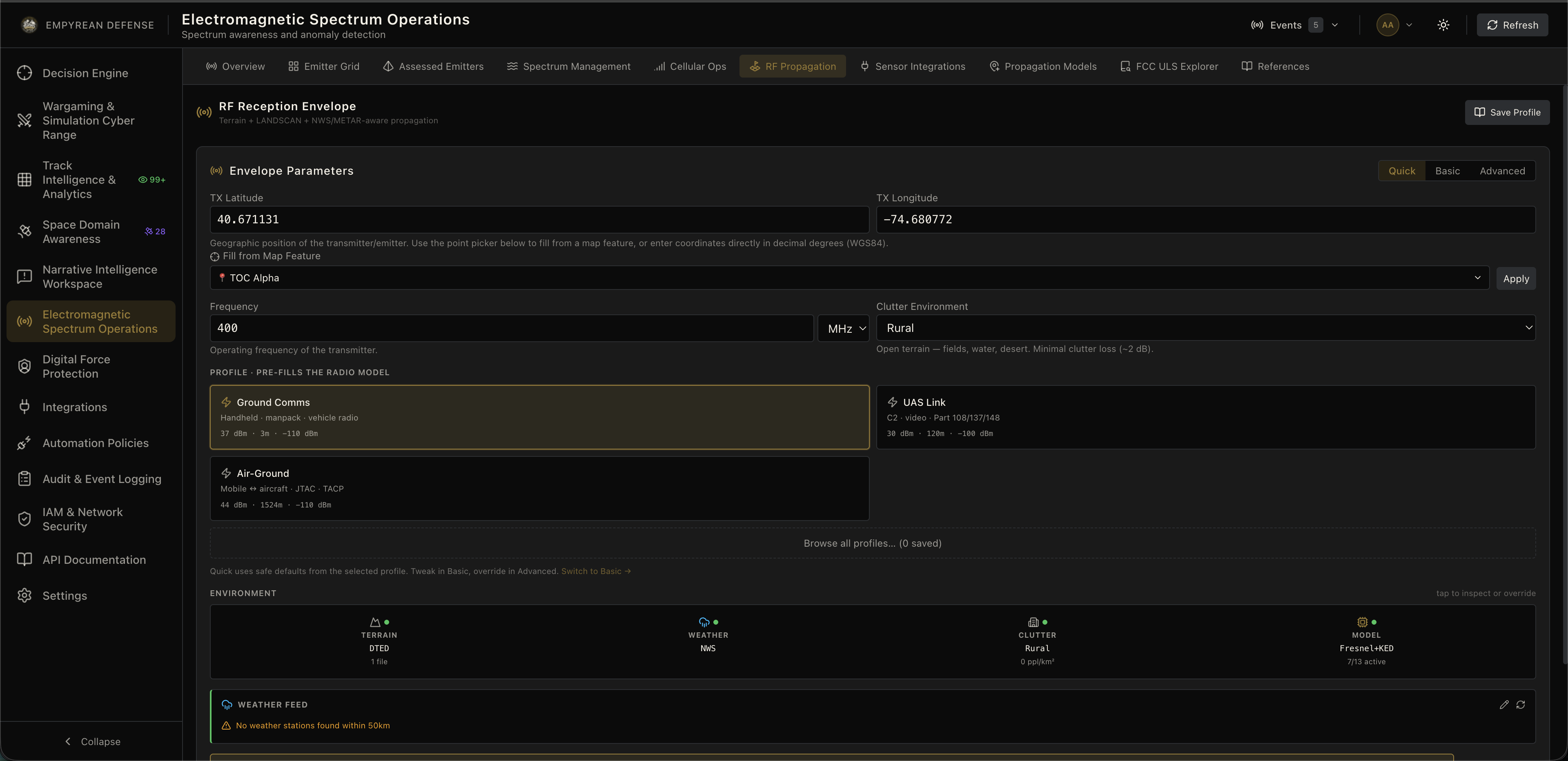
The reception envelope computes a terrain-aware RF coverage footprint for any emitter - your own sensors, threat systems, or infrastructure. The engine evaluates the complete link budget (EIRP, path loss, terrain loss, clutter, fade margin) along every radial and produces a polygon with "good reception" and "marginal reception" zones.
Three propagation model tiers are available: FSPL for quick planning with no terrain dependency, Fresnel and Knife-Edge Diffraction as the default when terrain is loaded, and ITM/Longley-Rice for maximum fidelity over long-range or complex terrain.
The computation completes fast enough for interactive "what-if" analysis without pre-computation - drag an emitter on the map, see the coverage update.
C2 Link Budget Assessment
For UAS BVLOS operations, maintaining command-and-control link is a safety-of-flight requirement. The platform evaluates link quality along every leg of a planned route:
The engine samples the route at configurable intervals (default: 500m), computes path loss from GCS to UAS at each sample using the selected propagation model, derives link margin above receiver sensitivity, and scores each leg. Scoring thresholds provide immediate operational guidance: 20 dB or above is robust, 10-20 dB is adequate, 3-10 dB is marginal, below 3 dB is poor, and below 0 dB is no link.
The methodology aligns with RTCA DO-377B's link budget analysis approach covering free-space path loss, atmospheric absorption, rain fade, and terrain effects. When rain rate data is available from the Weather Intelligence Service, ITU-R P.838-3 attenuation is applied per-sample along the route so the link assessment reflects current weather, not planning-day assumptions.
Cellular Operations and OpenCellID Integration
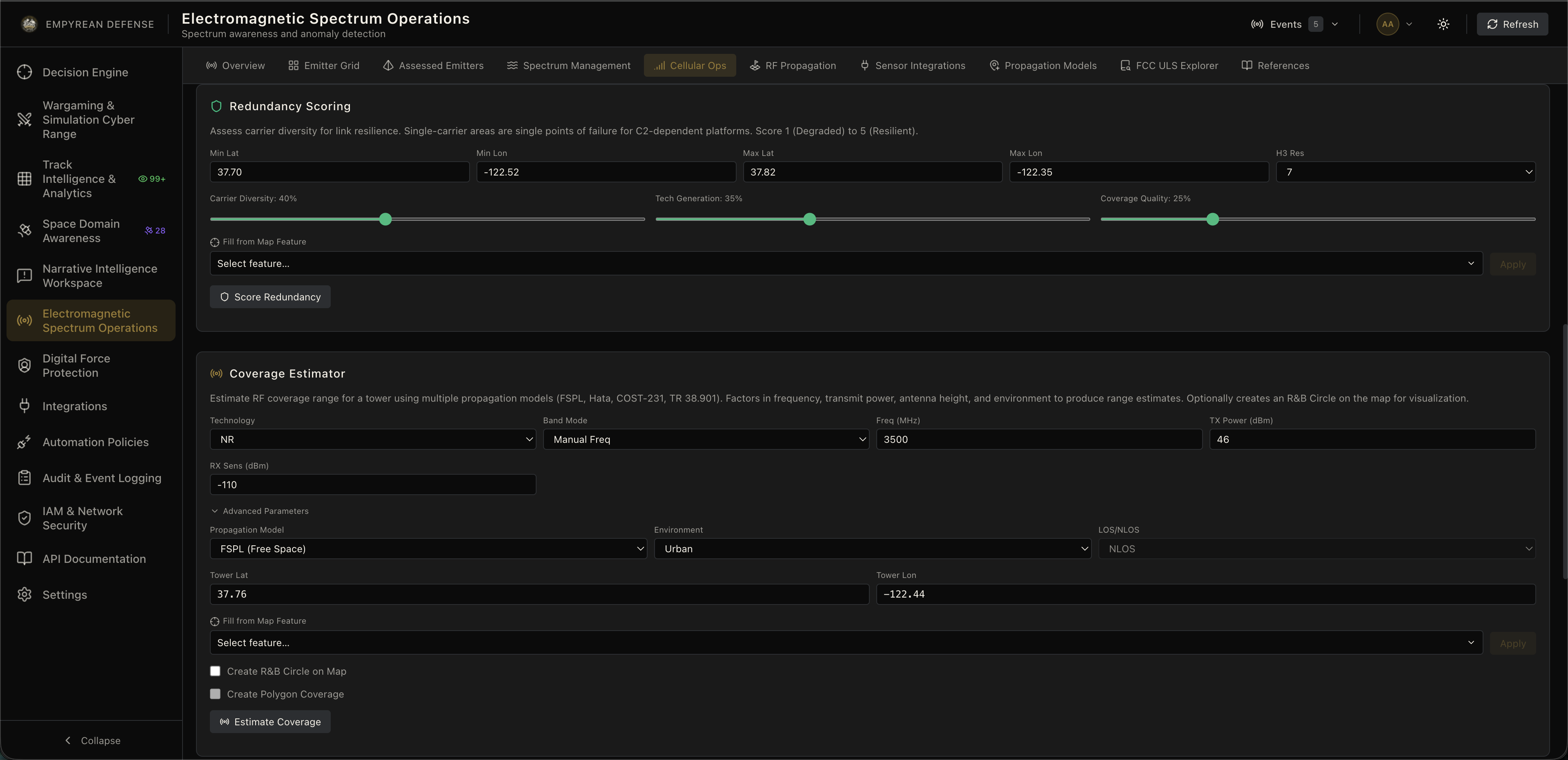
Empyrean ingests the global OpenCellID cell tower database - millions of tower records with location, radio access technology (GSM/UMTS/LTE/CDMA/NR), carrier identity (MCC/MNC), and frequency band. This powers three cellular-specific analysis modes:
Coverage Gap Analysis identifies geographic areas where tower density falls below a configurable threshold using an H3 hexagonal grid. These are dead zones where cellular connectivity cannot be assumed - critical for convoy route planning, emergency communications assessment, and understanding where adversaries might exploit communications gaps.
Multi-Carrier Redundancy Scoring evaluates each hex by carrier diversity, technology generation, and coverage quality. A hex with four carriers across LTE and NR scores higher than one with a single GSM tower. This tells operators where communications are resilient versus where a single tower failure creates a blackout.
Corridor Link Budget (Terrain-Aware) evaluates cellular coverage along a planned route using terrain-aware propagation with actual tower positions, heights, and frequencies from OpenCellID. Includes altitude sweep for airborne platforms, because cellular coverage at 400 feet AGL is very different from coverage at ground level.
Batch Propagation and Coverage Estimation
For planning scenarios that need to evaluate thousands of points simultaneously - "show me coverage from all 47 towers in this AOR" - the batch kernel processes arrays of frequencies and distances in a single vectorized pass. The coverage estimator combines model selection, max-range solving via binary search, and distance-versus-signal curve generation into a single API call.
Coming Soon
GNSS/PNT Integrity Monitoring — connecting space weather conditions (Kp index, solar radio flux, geomagnetic storm scales) to GNSS propagation degradation models, predicting when ionospheric scintillation will degrade positioning accuracy before it happens.
SATCOM Link Budget — extending the terrestrial propagation engine to space-to-ground paths with ionospheric effects (Faraday rotation, group delay, scintillation), tropospheric effects at slant-path elevation angles, and space weather correlation.
HF Propagation and Ionospheric Modeling — ionospheric layer heights, Maximum Usable Frequency (MUF) prediction, skip zone computation for skywave propagation, and D-layer absorption during solar flares. Connects the NOAA SWPC space weather feed to HF SIGINT sensor performance prediction.
Standards and References
| Standard | Application |
|---|---|
| Friis (1946) | Free-Space Path Loss baseline |
| Okumura et al. (1968) + Hata (1980) | VHF/UHF empirical propagation (150-1500 MHz) |
| EURO-COST 231 (1999) | PCS/DCS band extension (1500-2000 MHz) |
| 3GPP TR 38.901 V16.1.0 (2020) | 5G channel model (0.5-100 GHz) |
| ITU-R P.525-4 | Free-space attenuation |
| ITU-R P.526-15 (2019) | Fresnel zones, knife-edge diffraction |
| ITU-R P.530-17 | Earth curvature bulge |
| ITU-R P.676-13 (2022) | Gaseous atmospheric attenuation |
| ITU-R P.838-3 (2005) | Rain attenuation (power-law model) |
| NTIA Report 82-100 (1982) | Irregular Terrain Model (Longley-Rice) |
| NBS Technical Note 101 (1967) | Effective heights, terrain irregularity |
| Deygout (1966) | Multi-edge diffraction |
| RTCA DO-377B (2023) | UAS C2 link budget methodology |
Why This Matters
The electromagnetic spectrum is the contested domain that underpins every other domain. Air defense radars, tactical radios, cellular networks, GPS, SATCOM, UAS command links - they all propagate through the same physics. The difference between an operator who understands their RF environment and one who doesn't is the difference between confident action and dangerous assumption.
Empyrean's RF propagation stack doesn't ask operators to be RF engineers. It computes the physics, accounts for terrain and weather, integrates real infrastructure data, and delivers the answer in operational terms: your sensor covers here, your link holds to here, the emitter is probably between here and here, your cellular coverage fails at this point on the route.